Sunday, March 1, 2015

Frame Build Update


As my first several posts were heavy on fabrication details, I want to rewind a bit and provide more detail on the overall project scope. 
I receive a lot of questions about why wood? The answer is complicated but here are a few of the advantages and disadvantages of working with the material. 

Advantages: Wood is highly effective at reducing vibrations (up to 3x improved over carbon fiber), it has a higher resistance to impact damage, and has truly unique aesthetics as each piece of wood is different. Also, depending on fabrication techniques, wood is often a more sustainable approach than other materials. 

Disadvantages: Wood is not as strong or stiff as metals or other composites, and therefore more material is required to achieve equal frame strengh, and therefore increased weight. The material is also difficult to work with as it is sensitive to humidity and has natural flaws such as cracks or grain variations. 

The use of wood in bicycle frames is certainly not a new idea. Two US companies that are currently producing these types of frames are Renovo Bikes and Connor Cycles. The fabrication approach of these companies begins with hardwood boards which are laminated with epoxy and cut to shape on a CNC router. The two hollow halves are then bonded together to create the front triangle of the frame. They then require a high amount of sanding and finishing work before complete. 


My approach is a bit different. I have chosen to fabricate the wooden tubes separately. By using a this wood veneer coated in epoxy and rolled around tubes of various sizes, I am able to create lightweight and stiff tubes. I can closely control the properties of the tube by adjusting the wall thickness and number of layers of veneer. As wood is strongest in bending along the length of the grain, by altering the grain direction, I can also control the tube stiffness and torsional and crush strength. 

Additional benefits of this method are minimal sanding and finish work, very little material waste, and light weight. The overlapping grain in the various layers is also more resistant to crack propagation than solid wood.  

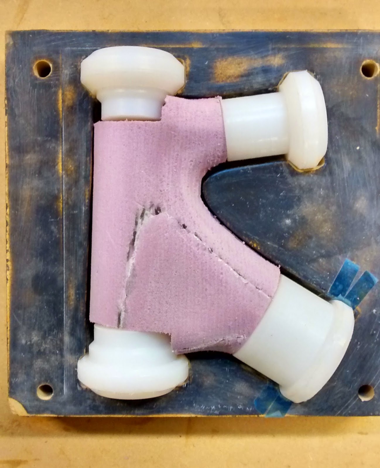
As seen in previous post and below, the areas where the tubes join, or lugs, are created by molding carbon fiber. The carbon is light and stiff, ideal for these tube junctions where high stress loads are seen. 


Above is a CAD screenshot of the carbon lug in black and the mold in gold. An insert is required since the seat stay tubes are angled. 


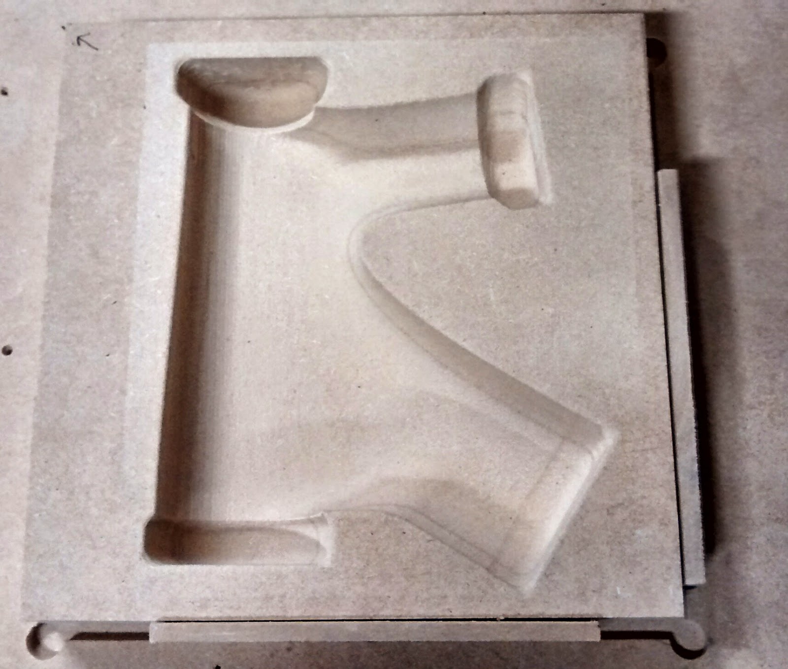
For a look at the fabrication progress, above is a look at the seat stay mold insert after cut on the CNC. 
Below is a mold half with along with the insert. These will later be primed and waxed before the carbon is molded. 


Stay posted for photos of the complete molds, including the bottom bracket mold and the frame jig where final frame alignment and bonding takes place. 


Tuesday, February 3, 2015

Carbon Headtube: part 2


Now that the mold prep is complete, it was time to turn my attention to creating the inflation bladder. This is critical in order to compact the layers of carbon against the mold for a consistent surface finish, and also to force out excess resin. The photo below is following the technique in this video: http://vimeo.com/10665397
I conducted several tests with various thickness plastic sheeting (1,2,& 4 MIL). Also required is parchment paper (not wax, it melts) and a soldering iron. 


After tracing the shape with the soldering iron and trimming the excess, a sealed bladder is created. I used the valve stem from an inner tube and a floor pump to apply pressure. After testing various shapes and material thicknesses in the closed mold to prevent excess expansion, I was only able to reliably attain 20 psi, far short of my goal. The tears would form at the concave portions of the bladder, I am confident a less complex shape would be successful. 


Below is one of the inflated bladders tested for size in the mold half. I opted away from this bladder solution since reliability is critical. and once the mold is closed there is no fixing. 


Instead, I reverted back to the approach on the previous mold test. I offset the headtube surface for the carbon thickness and cut two foam plug halves of the CNC. I then trimmed a channel in the center and fitted it with an inner tube that was cut and sealed to size. Once inflated, the tube pushes the foam halves apart and applies pressure on the outside surfaces. It will also provide adequate pressure on the parting seam, an area where the previous mold attempt fell short. 


Here is a look at the mold half with the UHMW inserts and foam core.  


The last step before molding was to determine an appropriate layup schedule: the orientation and number of layers of carbon in the part. The 6oz unidirectional carbon I am using is 3 inches wide, thus the majority of the layup pieces are that width. I tested the layup by cutting plastic sheeting and laying that over the foam core. Many of the pieces have slits that are not visible in the below photo, but that aid in wrapping tight against the core. Approximately 30 pieces total, with varied fiber direction, and more layers at higher stress areas of the headtube. 


I used several layers of woven sleeving as the base layer on the UHMW inserts, later wrapped in many 0 degree layers for a solid pocket for the integrated headset bearings. 


Layup was a bit tricky (and sticky) since I had to wet out each piece separately. I currently have the benefit of a cool shop (50F) which extends the workable life. In the future I will wet out a long stretch of fabric, then cut to size. Or better yet, get my hands on some carbon prepreg. 
This material is much easier to work with since it already contains a precise amount of epoxy from the supplier, so no mess as with the wet layup. Downsides are the cost (often twice as expensive and only available in bulk), required refrigeration to prevent curing, and cure temperatures of 250-350F. As a reference, the epoxy system I am using cures in 24 hours at room temperature (~75F). 


Above is the first look once the mold was opened. The mold halves separated very easily, which is a testament to the correct primer, wax, pva coats discussed earlier. As you can see there is excess flash indicating perhaps a bit too much epoxy. 
I was a bit hasty in closing the mold which led to fibers being caught between the two halves, which was later trimmed and results in a less than desirable aesthetic. 


Here is the final trimmed part with the lower bearing installed. The fit is just slightly loose, most likely due to a cure temp slightly higher than anticipated, causing excess UHMW expansion. Overall extremely pleased with the surface finish (there is no surface finishing except sanding of the seam). I am also please with the lack of void or air bubbles visible in the part.

Below is a look at the molded bearing cups. The part weighs in at a hefty 255 grams. It is definitely overbuild, but I have no concern about it failing. A future revised layup schedule will focus on reducing the weight and bulk of the part. 


With this complete, I will next turn my attention to the seat tube and bottom bracket lugs. 

Sunday, February 1, 2015

Carbon Headtube


Above is a revised mold half with slightly adjusted geometry and pockets for the mold plug inserts. This time around I chose to seal the MDF molds and prep for release. First step was to coat it with surface primer, Duratec 707, which is easily sand-able. I applied with a brush since I don't yet own a spray gun...not advised. The brush marks were difficult to sand out and I ended up applying additional thicker coats. 

This was followed by sanding/polishing 400 -> 2000 grit. I then applied ~6 coats of Partall wax and two coats of PVA mold release film. The near completed molds are shown below. I later did some dremel work to expand the pockets for the plugs since finishing pass was with a 1/2" ball end mill, I didn't get the desired detail. 


During the first molding attempt, the curing time was extended due to low temperatures in the shop. To better control the cure process, and to post cure providing better epoxy cross-linking, I build a small oven. The simple setup is insulating foam with a 60W light bulb as the heating source. This will ramp up to 160F in about an hour. Initial cure will be 24 hours at ~70F and then several hours at ~150F. I also use this to warm the epoxy before mixing as the viscosity is far too high as 50F. 


Next step was to fabricate the mold plug inserts to control the ID of the tubes. I chose to use UHMW PE which is largely epoxy-phobic. This material does have a high rate of thermal expansion, so these were cut undersized to allow for expansion during cure.  
A lathe would be ideal, but I opted to use the router with some creative clamping. 


The photo below shows the mold with the plastic inserts. For the headtube I am attempting to direct mold the integrated bearing cups. This will save cost and weight as press in bearing cups aren't required. 


Keep posted for the layup of headtube lug V2. Thanks to Adam and Rob for advice on the mold creation and layup process. 


Carbon Mold Test


I have done lots of research on composite molding over the past several weeks and it is now time to get my hands dirty. After tweaking the desired frame geometry in the CAD model, I am ready to cut a test mold for the headtube. Photo above is the finishing pass, and I am not overly concerned with surface finish quality at this point. 
Below is a mold half with the CNC cut foam core, offset the desired wall thickness. The foam provides a shape to wrap the carbon during the wet layup. It will also provide better compaction of the carbon in the tighter radius portions of the mold. 


  The MDF mold is a very porous material and the epoxy will adhere to it. As a shortcut mold release, I lined the mold with packing tape, since the epoxy wont stick to it. The foam core is also wrapped in plastic sheeting and tape to aid in the remove post layup. In order to get better compaction in the mold, a latex bladder is typically used. Another shortcut here, I have used an inner tube to provide compaction. I will inflate to ~40psi once the mold is closed.  


As this was just a test, I only used three layers of 6oz unidirectional carbon fiber sourced from Soller Composites. The resin system used is Adtech 820 with the 822 hardener. After 24 hours in the mold, results are show below, on the right with after trimming and flash removal.  


Surface finish is quite good with the exception of wrinkles from the tape mold lining, which was expected. 
The next step is to fabricate another mold, this time with inserts to control the ID for headset installation and top/down tube junctions.


How it Began


It began in 2011 as a graduate design project on the design and fabrication of a wooden bicycle. The photo above is the first attempt at an all wooden frame, which I fondly refer to as V1. It has since been retired as it underwent some structural testing till failure. Many of the weaknesses of V1 were improved upon in V2, which has yet to be completed as seen below.


Fast forward a few years and we are back on track. With a dedicated workshop and a CNC router, I am now working on the projects full time. 


Back to the drawing board for 2015 to investigate new techniques for frame fabrication including mitered tube to tube and various composite lug moldings. Enjoy reading and I appreciate any comments and feedback!