Now that the mold prep is complete, it was time to turn my attention to creating the inflation bladder. This is critical in order to compact the layers of carbon against the mold for a consistent surface finish, and also to force out excess resin. The photo below is following the technique in this video: http://vimeo.com/10665397
I conducted several tests with various thickness plastic sheeting (1,2,& 4 MIL). Also required is parchment paper (not wax, it melts) and a soldering iron.

After tracing the shape with the soldering iron and trimming the excess, a sealed bladder is created. I used the valve stem from an inner tube and a floor pump to apply pressure. After testing various shapes and material thicknesses in the closed mold to prevent excess expansion, I was only able to reliably attain 20 psi, far short of my goal. The tears would form at the concave portions of the bladder, I am confident a less complex shape would be successful.

Below is one of the inflated bladders tested for size in the mold half. I opted away from this bladder solution since reliability is critical. and once the mold is closed there is no fixing.

Instead, I reverted back to the approach on the previous mold test. I offset the headtube surface for the carbon thickness and cut two foam plug halves of the CNC. I then trimmed a channel in the center and fitted it with an inner tube that was cut and sealed to size. Once inflated, the tube pushes the foam halves apart and applies pressure on the outside surfaces. It will also provide adequate pressure on the parting seam, an area where the previous mold attempt fell short.

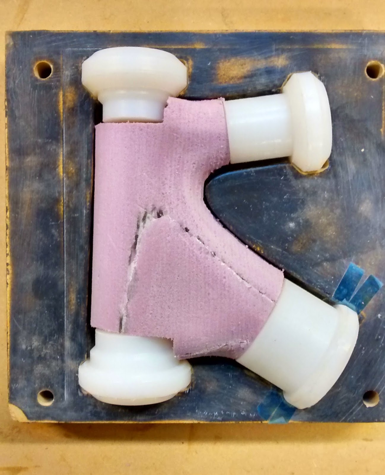

I used several layers of woven sleeving as the base layer on the UHMW inserts, later wrapped in many 0 degree layers for a solid pocket for the integrated headset bearings.

Layup was a bit tricky (and sticky) since I had to wet out each piece separately. I currently have the benefit of a cool shop (50F) which extends the workable life. In the future I will wet out a long stretch of fabric, then cut to size. Or better yet, get my hands on some carbon prepreg.
This material is much easier to work with since it already contains a precise amount of epoxy from the supplier, so no mess as with the wet layup. Downsides are the cost (often twice as expensive and only available in bulk), required refrigeration to prevent curing, and cure temperatures of 250-350F. As a reference, the epoxy system I am using cures in 24 hours at room temperature (~75F).

Above is the first look once the mold was opened. The mold halves separated very easily, which is a testament to the correct primer, wax, pva coats discussed earlier. As you can see there is excess flash indicating perhaps a bit too much epoxy.
I was a bit hasty in closing the mold which led to fibers being caught between the two halves, which was later trimmed and results in a less than desirable aesthetic.

Here is the final trimmed part with the lower bearing installed. The fit is just slightly loose, most likely due to a cure temp slightly higher than anticipated, causing excess UHMW expansion. Overall extremely pleased with the surface finish (there is no surface finishing except sanding of the seam). I am also please with the lack of void or air bubbles visible in the part.
Below is a look at the molded bearing cups. The part weighs in at a hefty 255 grams. It is definitely overbuild, but I have no concern about it failing. A future revised layup schedule will focus on reducing the weight and bulk of the part.


With this complete, I will next turn my attention to the seat tube and bottom bracket lugs.
No comments:
Post a Comment